
| | Home | Contact us | |
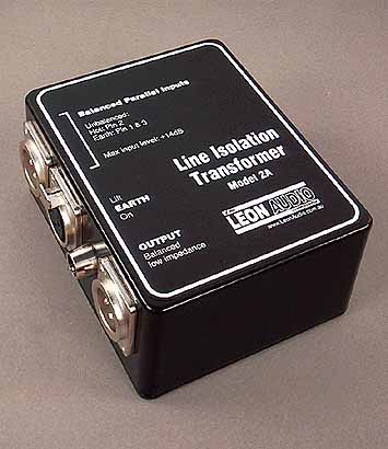
| Line Isolation Transformer |
| Description |
Suitable for the most demanding of situations in both live and recording applications.
A no-compromise audio isolation transformer that provides extremely high sound quality and the maximum possible rejection of external electrical interference, such as dimmer buzz.
The transformer also provides excellent isolation of large common mode (earth) voltages due to an optimised internal design. This translates into excellent performance when isolating input and output circuits.
An optimally balanced output, provided by the transformer, is ideal for driving long balanced cables, such as multicores.
The fully floating balanced input and output are able to accept either
3 conductor balanced circuits or 2 conductor unbalanced circuits, providing
an ideal unbalance/balanced or balanced/unbalanced interface.
When used with unbalanced inputs or outputs, the unused pin must be
tied to earth for correct operation.
Effective screening against hum pickup from nearby transformers, such as those in power amplifiers, is provided by a MU metal shield which totally encloses the transformer.
A parallel loop through connector is provided on the input.Totally passive
design means that no batteries are required.
| Specifications |
All measurements made with 50 ohm source impedance
and 600 ohm load impedance. 0dBu=0.775Volts
| Frequency Response
Common Mode Rejection Ratio Recommended Source Impedance Recommended Load Impedance Maximum Input Level Total Harmonic Distortion (THD) Power Supply Finish Weight Dimensions |
30Hz - 15kHz ±1.5dB
>115dB (see test circuit) less than 100 ohms 600 ohms or higher +14dBu 0.05%, 30Hz - 20KHz at +14dBu None required Powder coated die cast aluminium 510 grams net. W 95mm H 120mm D 67mm |
| A Few Isolation Topics |
Earth Loops
An earth loop can occur when 2 pieces of audio equipment are connected
together.
Lets take a musicians keyboard and connect it directly to a mixing
desk. The keyboard is connected to the mains earth via more than one path.
The first path is via the instruments own power cable to the mains earth.
The second path is via the interconnecting audio cable to the mixing desk,
then via the mixing desks power cable back to the mains earth. This is
an earth loop.
If there is any difference in the voltage between the two mains earth
connections, a circulating earth current will flow and is amplified and
manifests itself as a hum or buzz.
Connecting both pieces of sound equipment to the same power source
will often reduce the magnitude of the circulating earth currents, but
they will still be there.
Using a balanced interconnection will often reduce the effects of circulating
earth currents, but the currents will still be there. In this case, how
much noise is heard is very equipment dependent as it depends a lot on
where the earth currents flow inside each piece of equipment.
Earth loops are often fixed by cutting the mains earth wire in the
power lead of one of the pieces of equipment. This is a very unsafe practice,
because should a fault occur, electrocution is a possibility. A technically
correct solution is to use an audio isolation transformer.
Transformer Isolation
An audio isolation transformer connected between two pieces of equipment
will prevent the flow of circulating earth currents. This is because there
is no electrical connection between the input and output of the transformer.
The audio signal is coupled magnetically.
So you go out and buy a Radio Shack, or similar, audio transformer,
connect it up and you still get earth noise and it now sounds distorted
as well.
So what went wrong?
A budget transformer will have insufficient (if any) screening between
its input and output. While there is no direct DC connection, as measured
on the ohms range of a multimeter, there is considerable capacitive coupling
between the windings. Audio frequency signals will simply hop from the
input to the output winding if there are no screens to prevent this.
Substantial screening is required to prevent capacitive coupling. One screen
is often inadequate.
A magnetic shield is also required to prevent external magnetic fields
from generating unwanted signals into our transformer. One common source
magnetic interference is the power transformer in the power supply of virtually
every piece of mains operated equipment. The solution is to enclose the
transformer in a MU metal case. MU metal is a nickel/iron laminate with
excellent magnetic screening characteristics.
The main source of audible distortion in an el-cheapo transformer would
come mainly from saturating the transformer core at low frequencies. The
solution is to use a core of sufficient size to give adequately low distortion
figures at the lowest frequency of interest (usually 20Hz) and at the maximum
signal levels to be handled. If the low frequencies are rolled off, it
is often possible to get a transformer to handle signals above its design
maximum while still maintaining low distortion figures.
The Leon Audio Isolation Transformer incorporates multiple screens to achieve the best possible isolation of capacitively coupled signals. The transformer is totally enclosed in a MU metal case. A large core enables distortion of only 0.05% at 30Hz while passing a +20dB signal (RS = 50 ohms, RL= 600 ohms)
Transformers are almost always better at interfacing to balanced lines
than the electronic circuits commonly used in audio equipment to provide
balanced inputs and outputs. Even though the equipment may be balanced
in terms of legal/advertising requirements, problems can still be experienced.
Electronic designs usually fall short of what is required technically to
perform well under adverse conditions. A classic case of electronic
design by accountants.
Common Mode Rejection
This is the ability of a device to reject any signal that is common
to both of its input terminals with reference to the output circuit. The
most common case is where a signal source is connected to a different power
source to that of the load. While the voltage on each of these 2 power
sources earth wires should ideally be zero, this is rarely the case. The
test circuit uses 2 x 330 ohm resistors to provide a balanced source. This
source has a few volts of earth noise (with reference to the output circuit).
In this case, the earth noise is 240 volts 50Hz AC. A pretty severe case.
The load is a 10K ohm resistor in parallel with a millivolt meter.
![]()
![]() Common
Mode Test Circuit
Common
Mode Test Circuit
In the common mode test circuit the meter measured 0.1mV which equates to a Common Mode Rejection Ratio (CMRR) of 115dB. It also equates to an output 65dB below 0dB (.775V)
In the real world, earth voltages are usually much less than 240V (<5V is typical), so we can expect any noise due to earth voltages to be buried in the signals noise floor.
Note: The above tests were carried out under controlled conditions.
These transformers are NOT
rated for connection to 110/240 volt mains, nor are they intended to provide
safety isolation from dangerous voltages.
| 2 Year Warranty |
The Isolation Transformers are guaranteed for two years from date of
original purchase against defects in workmanship and materials.
If such malfunction occurs, the item will be repaired or replaced (at
our option) without charge for materials or labour if delivered prepaid
to THE LEON AUDIO COMPANY. Unit will
be returned prepaid. Warranty does not cover finish or malfunction due
to abuse or operation at other than specified conditions. Repairs by other
than THE LEON AUDIO COMPANY or authorised agents will void this guarantee
| Brochure |
| Download this page as a PDF file
line_iso.pdf (200Kb) in Adobe Acrobat format |
| Home | To top | Contact us |
Copyright © 2024. The Leon Audio Company. All rights reserved.